
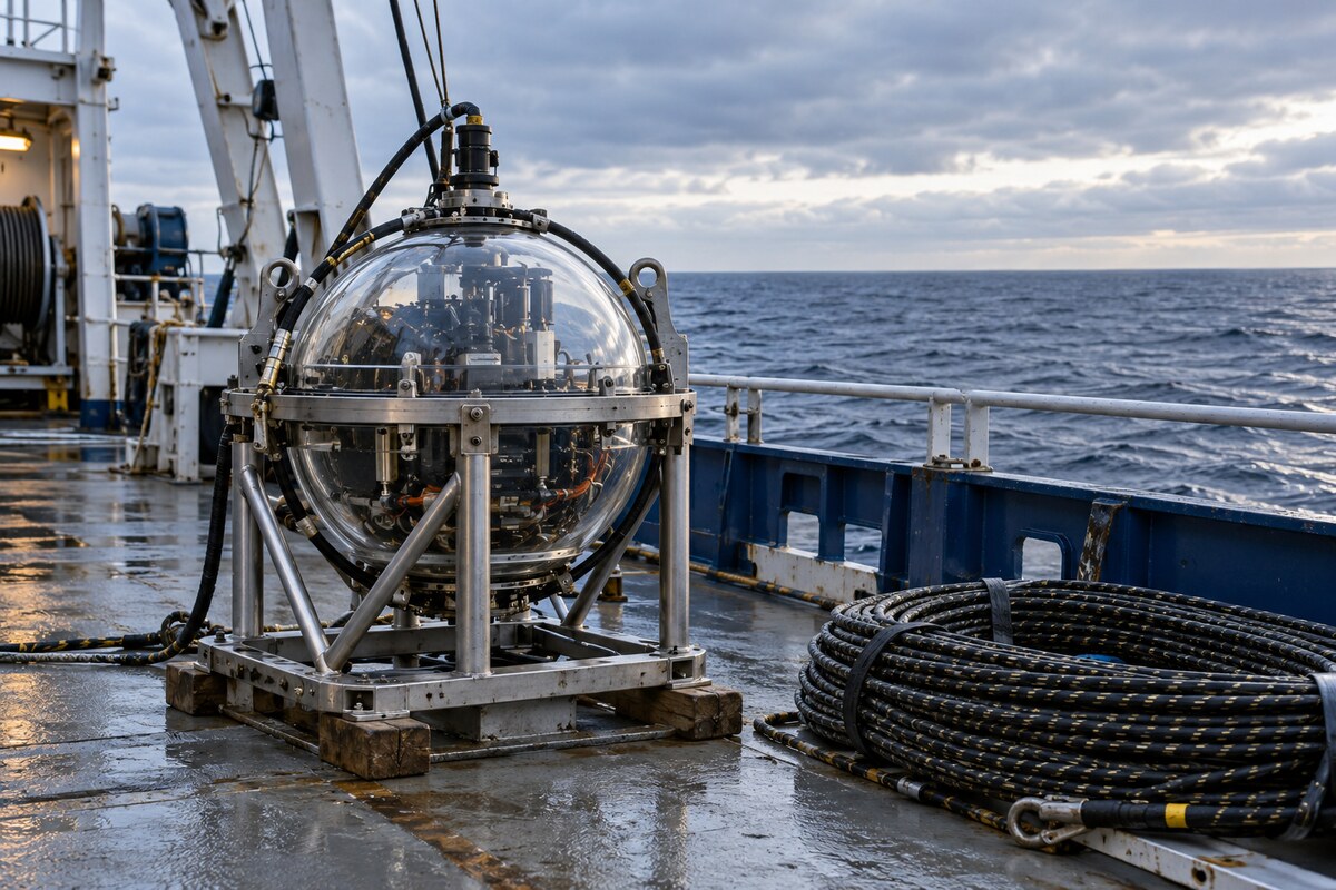
An array beneath the sea
TRIDENT, the Tropical Deep-sea Neutrino Telescope, is proposed for water about 3,500 metres deep in the South China Sea. Chief scientist Xu Donglian and project head Jing Yipeng work at Shanghai Jiao Tong University in China. The 2023 concept specified 1,211 strings, each roughly 700 metres long with 20 optical modules, separated horizontally by 70 or 110 metres. Its approximately four-kilometre diameter would encompass 12 square kilometres and instrument about 7.5 cubic kilometres of water.
Near the equator, Earth’s rotation would extend sky coverage. The planned operating life was 20 years; detecting the galaxy NGC 1068 in Cetus within a year was a sensitivity forecast. In January 2024, the ten-string first phase was targeted for 2026 and the full telescope for around 2030. These were construction and scientific expectations. The engineering work spans pressure-resistant instruments, calibrated light, synchronized electronics and reconstruction of rare particle interactions.
Housing light inside glass
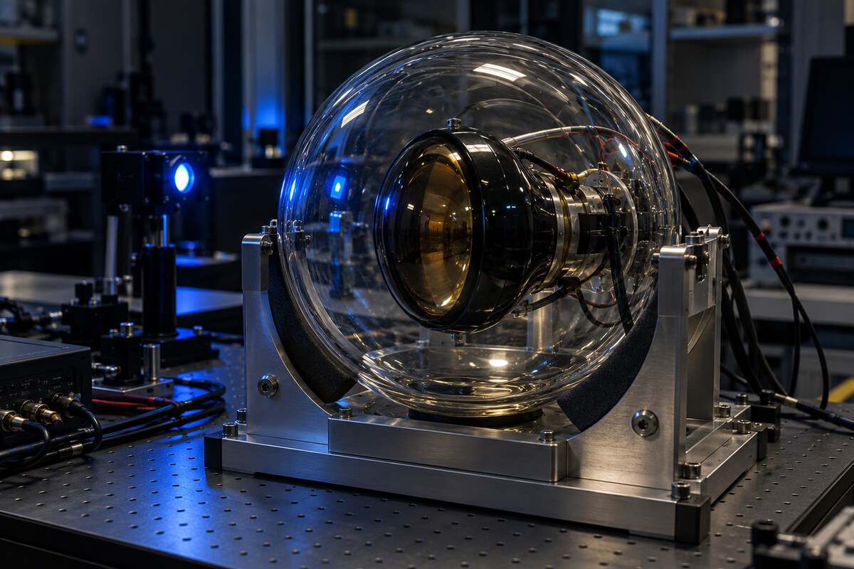
The pathfinder’s light emitter enclosed its components in a 17-inch glass sphere, 432 millimetres across with a 14-millimetre wall. Two hemispheres formed the housing; one carried a vacuum port and a penetrator for connections. Before deployment, the instrument underwent pressure tests between 38 and 45 megapascals, lasting from two to 24 hours. Some tests included ice to reproduce cold conditions. These were qualifications for the prototype experiment, rather than a demonstration of decades of operation on the seabed.

Inside, a printed resin support held the electronics between two hemispherical diffusers. Small polytetrafluoroethylene balls provided the first diffusion stage; a second, printed shell distributed the light more broadly. Slots, shelves and cable openings accommodated the boards without placing them across the principal emitting surfaces. Ports, wires and structural parts nevertheless produced shadows and unequal brightness between the two sides. Laboratory measurements mapped that emission pattern for use in analysis. The resin supports were adequate for the short experiment, while their stability in long deployments still required testing.
Pulses and steady illumination
The emitter supplied two different optical measurements. Brief LED flashes served the photomultiplier tubes, while steady illumination served the cameras. A tunable driver generated pulses roughly three nanoseconds wide, substantially shorter than the arrival-time distribution broadened by scattering in water. Operators could adjust intensity, wavelength and repetition frequency from the research vessel. The driver used a capacitor-discharge circuit, with a complementary transistor switch producing the narrow electrical pulse and an inductor helping shorten its duration.
An automatic voltage scan established suitable brightness under the actual attenuation encountered at sea. Software examined the proportion of single-photoelectron signals as it changed the LED supply setting. During the 2021 expedition, the pulsing system operated at 10 kilohertz, with an average photon count of about 0.3 per acquisition window in the stated operating condition. The laboratory commissioning used a different mean count of 0.1. Constant-current drivers powered the steady LEDs, limiting brightness changes associated with heating. Pulsed blue light used a nominal wavelength of 450 nanometres; the corresponding steady blue source used 460 nanometres.

Selecting and calibrating receivers
Six three-inch photomultiplier tubes, or PMTs, were selected from a tested sample of 50 for the two receiver modules. The HZC XP72B22 devices were assessed for quantum efficiency, dark counts, transit-time spread, separation of the single-photoelectron peak from background, and signal amplitude. Those properties governed both photon counting and timing. Because deployment exposed the tubes to light, the team also tested recovery of their dark-count rate after illumination. Typical recovery took about 30 minutes, shorter than the deployment process.
Calibration continued after assembly in a dark room near two degrees Celsius. The experiment compared receiver sensitivities and the brightness of the emitter’s two hemispheres, swapping combinations and rotating the receivers to average orientation effects. Air measurements established the combined timing response of LEDs and PMTs before water scattering was introduced. A PMT afterpulse produced a delayed shoulder in the signal distribution and had to remain distinct from the longer seawater scattering tail. During sea measurements, high-noise intervals were removed; correlations between tubes in the same receiver were tentatively associated with apparatus vibration.
Cameras measure the light field
Two cameras provided an independent view of the illuminated emitter during the September 2021 pathfinder mission. At a depth of 3,420 metres, they collected about 3,000 images in roughly 30 minutes. Each monochrome camera had five million pixels and a 25-millimetre lens. A Raspberry Pi controlled acquisition and transmitted images and sensor readings through the cable’s optical fibre to the vessel. A local memory card retained a duplicate copy against transmission losses. Temperature, humidity and orientation sensors accompanied the imaging system.

The central image region concentrated directly arriving light, while surrounding pixels included a scattering halo. Comparing the central brightness at two distances provided an attenuation measurement; a separate fit of image profiles against simulations helped distinguish absorption from scattering. Laboratory work checked linear response, low-temperature behaviour and underwater focus. Refraction through the curved glass housing required calibration in a ship-model towing tank. Exposure and gain settings accommodated changing illumination without saturation. The compact system was intended for rapid optical calibration distributed through a future array; autofocus and further calibration refinements remained prospective upgrades.
Keeping acquisition synchronized
The pathfinder’s readout connected submerged modules to a data-acquisition computer on the research vessel. White Rabbit timing travelled over optical fibres to synchronize module clocks. A global-trigger mode coordinated LED flashes with the PMTs, while a self-trigger mode recorded signals exceeding a threshold for ambient-background measurements. PMT waveforms were digitized at 250 million samples per second with 12-bit converters. Field-programmable gate arrays buffered the data and assembled events containing channel identifiers, timestamps, event numbers and a waveform segment.
A cyclic redundancy check accompanied each event packet. Separate buffers and status registers let operators monitor acquisition, including overflow conditions. Configuration values were read back after changes, allowing the control software to verify that a command had taken effect. The vessel-side system distributed commands, collected waveforms and images, displayed live measurements and saved binary data for later analysis. Aluminium plates and copper pillars supported heat removal and electromagnetic shielding inside the receivers. Firmware could be programmed without reopening a sealed module before deployment; this facility did not provide a wireless connection through deep seawater.

Larger silicon sensors, constrained channels
TRIDENT’s hybrid optical-module concept combines PMTs with silicon photomultipliers, or SiPMs. Expanding the silicon detection area creates an electrical constraint: connecting more devices in parallel increases capacitance, reducing signal amplitude and slowing the waveform edges used for timing. Providing an individual amplifier for every small sensor would instead consume space, power and readout channels inside the sphere. The 2024 discrete-electronics development combined series and parallel connections, a transformer-based preamplifier and analogue summation to collect signals from a larger area through fewer channels.
A four-by-four array of Hamamatsu S13360-3050PE devices provided a detection area of 12 by 12 millimetres. Bench measurements achieved approximately 300 picoseconds full width at half maximum for single-photon timing, with total front-end consumption below 100 milliwatts. That result characterizes the tested sensor-and-electronics configuration, rather than the pointing accuracy of the proposed telescope. The circuit work also examined noise, signal-path differences and variations between sensors’ breakdown voltages. Matching device characteristics and choosing the trigger threshold were part of controlling timing spread in the combined array.
Testing an integrated readout
A subsequent study, released on Feb 5, 2025, investigated custom integrated circuits for the silicon readout. Two test chips fabricated in a 180-nanometre CMOS process compared four combinations of input stages and discriminators. Common-gate and negative-feedback input stages were paired with current or voltage discrimination. The circuits determined when a sensor signal crossed a threshold. A digital OR arrangement combined outputs, reducing the number of connections leaving the sensor assembly; an external FPGA-based time-to-digital converter completed the timing measurement.

Tests with single SiPMs achieved timing resolutions around 260 picoseconds full width at half maximum. A configuration with two devices in series and two such branches in parallel met a timing-jitter requirement below 500 picoseconds, with consumption below seven milliwatts per channel. These are separate test configurations and power bases from the earlier discrete sixteen-device array. The researchers identified voltage discrimination as less sensitive to process, voltage and temperature variation. The fabricated chips established candidate architectures for a future fully functional readout, rather than demonstrating mass production or complete detector operation.
Measuring the muon background
Atmospheric muons can penetrate substantial depths of water and form a background to neutrino searches. MuonSLab measured that background using four plastic scintillator slabs read by silicon photomultipliers. A trigger requiring signals in at least three slabs helped suppress lower-energy backgrounds. An inclinometer and depth gauge recorded the instrument’s orientation and position in the water column. Batteries, digitizing electronics and local storage made the detector self-contained, while an additional junction box housed backup equipment. Its glass vessel also tested components relevant to future TRIDENT instruments.
Before sea deployment, the operating detector passed a pressure test reaching 40 megapascals, with the maximum pressure maintained for 20 hours. Cold-room testing between two and three degrees Celsius lasted more than 48 hours. Two trials during T-REX 2024 then recorded muons at different depths: an approximately four-hour trial collected more than 1,500, and a second, roughly two-hour trial collected 357. Measurements extended to about 2.1 kilometres below sea level. Those observations concerned atmospheric muons, not astrophysical neutrino detections. The resulting depth-dependent measurements support checks of background simulations and trigger development.

Simulating photons through seawater
The optical simulation followed photons individually through absorption and scattering using Geant4. To increase efficiency, the virtual receiver was expanded into a shell surrounding the emitter. This symmetry-based construction collected more simulated photon trajectories than a small physical receiver would intercept. Weighting accounted for the real emitter’s non-uniform output. Recorded photon positions, directions and arrival times could then be transformed into camera images or PMT arrival-time distributions. Laboratory calibration of the instrument response was included when comparing simulations with the pathfinder’s measurements.
The calculations distinguish several optical quantities that otherwise look similar. A camera’s central image region selects light by direction, whereas a PMT receives photons over a wider range of directions and also measures their arrival times. Counting every detected photon therefore produces an effective attenuation length that includes scattered light; it does not directly reproduce the canonical attenuation length for a narrow beam. The simulation examined these differences and tested analysis methods against known input parameters. Its scope was the interpretation of calibration data and validation of optical analysis, rather than an additional observation of cosmic neutrinos or a new sea expedition.
Reconstructing an interaction
A graph-neural-network approach represented each triggered optical module as a node, with connections to nearby nodes. Module positions and measured light information became the graph’s attributes. Muon-neutrino interactions can create long tracks, while electron-neutrino interactions produce more localized showers; the reconstruction treated those topologies separately. Interaction and detector simulations used CORSIKA8, Pythia8 and Geant4, with GPU-assisted propagation of optical photons through OptiX. These generated samples trained and tested the method against known particle directions, rather than against events observed by a completed telescope.

The shower study used electron-neutrino events at 100 teraelectronvolts because simulation speed limited the available samples at other energies. Its median directional error was about 1.3 degrees, compared with a cited likelihood-method result near 1.7 degrees. The track approach first estimated photon-emission positions and then fitted a line through them, reaching roughly 0.1-degree resolution for sufficiently energetic events. Training and evaluation also applied different minimum-node selections. Extending reconstruction across a wider range of energies and testing robustness against noise and experimental uncertainties remained further work, so these results retain their specific simulation conditions.
From prototypes to deployment tests
The TRIDENT collaboration’s October 2025 progress account identifies four verification modules with seven PMTs each in October 2024. A prototype string was deployed during November–December 2024 and recovered in March 2025. The team completed a first set of hybrid-module electronics in July and a first fully functional hDOM in September 2025. These milestones concerned prototypes and their integration. They did not establish that the full astronomical array had been installed or that its projected source sensitivity had been achieved.
The SPIDER deployment carrier progressed from a quarter-scale unfolding model in 2023 to a March 2025 test in Qiandao Lake, a May deep-sea functional trial and two August tests with different model payloads. The collaboration reported controlled release and unfolding. As of October 2025, its ten-string first phase still targeted underwater installation in 2026. Its longer-term description envisaged approximately 1,000 strings and ten cubic kilometres, differing from the earlier conceptual layout. Both specifications describe evolving plans; neither is a measurement of an operating full array.

Choosing geometry around the water
An October 2025 optimization study held the number of strings and modules fixed while varying their spacing, height and clustering. Its reference used 1,000 strings with 20 modules each, 100-metre average horizontal separation and 30-metre vertical spacing. The comparison evaluated the simulated time required to reach a five-standard-deviation point-source discovery threshold for assumed source spectra. It incorporated both tracks and cascades. The calculations excluded contributions from SiPMs, bioluminescence, positioning uncertainty and spatial or temporal changes in the water’s optical properties.
The modeled design choices produced different trade-offs:
- Wider spacing enlarged the volume but reduced photon statistics and low-energy reconstruction performance.
- Taller strings offered moderate gains subject to deployment and current-related constraints.
- Separated clusters introduced gaps and more edge events, worsening most channels, with an exception for soft-spectrum cascades.
In the tested optical scenarios, reducing attenuation length by 20% increased the simulated discovery time by factors of two to four. These were relative model results under specified assumptions, not construction delays or measured telescope performance. Initial deployments and continuing optical calibration were intended to supply the environmental inputs for subsequent design decisions.


















Leave a comment